RDR
Name |
Read ROM Port |
Function |
The data present at the input lines of the previously selected |
Syntax |
RDR |
Assembled |
|
Binary |
11101010 |
Decimal |
234 |
Hexadecimal |
0xEA |
Symbolic |

|
Execution |
1 word, 8-bit code and an execution time of 10.8 \({\mu}\) sec |
Side-effects |
Not Applicable |
Implemented |
Detailed Description
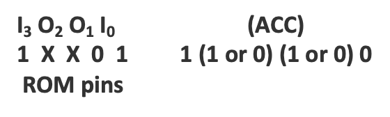
The ROM port specified by the last SRC instruction is read. When using the 4001 ROM, each of the 4 lines of the port may be an input or an output line; the data on the input lines is transferred to the corresponding bits of the accumulator. Any output lines cause either a 0 or a 1 to be transferred to the corresponding bits of the accumulator.
The opcode for this instruction does not contain any additional data:

Example
The following instructions will read the contents of the port associated with ROM number 10 into the accumulator.
/ Example
        FIM   3P    160
        SRC   3P
        RDR
The rdr operation above is carried out as follows:
   Accumulator   =   1 0 1 0
Data Character   =   0 1 1 1
Carry            =         0
                     -------
   Result      1     0 0 0 1
The accumulator contains 1 and the carry bit is set.
If the leftmost I/O line is an output line and the remaining I/O lines are input lines containing 010b, then the accumulator will contain either 1010b or 0010b.
Note
On the INTELLEC 4, a ROM port may be used for either input or output. If programs tested on the INTELLEC 4 are to be run later with a 4001 ROM, the programmer must be careful not to use one port for both functions.
Note
Whether a 0 or a 1 is transferred is a function of the hardware and not under
control of the programmer. That is to say, when a 4001 ROM chip is ordered,
it is required to determine at that stage what the functionality of the pins
should be. Once ordered, the decision cannot be reverted. An order form can be
downloaded here
