Branch Table Pseudosubroutines
Suppose a program consists of several separate routines, any of which may be executed depending upon some initial condition (such as a bit set in the accumulator). One way to code this would be to check each condition sequentially and branch to the routines accordingly as follows:
CONDITION = CONDITION 1 ?
IF YES BRANCH TO ROUTINE 1
CONDITION = CONDITION 2 ?
IF YES BRANCH TO ROUTINE 2
        .
        .
        .
        .
BRANCH TO CONDITION N
A sequence as above is inefficient, and can be improved by using a branch table.
The logic at the beginning of the branch table program computes an index into the
branch table. The branch table itself consists of a list of starting addresses for
the routines to be selected. Using the table index, the branch table program loads
the selected routine’s starting address into a register pair and executes a
“jump indirect” to that address.
For example, consider a program that executes one of five routines depending
upon which bit (possibly none) of the accumulator is set:
Jump to routine 0 if accumulator = 0000
Jump to routine 1 if accumulator = 0001
Jump to routine 2 if accumulator = 0010
Jump to routine 3 if accumulator = 0100
Jump to routine 4 if accumulator = 1000
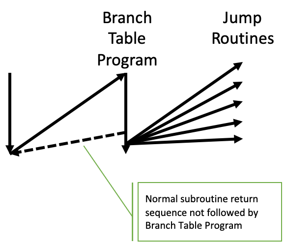
A program that provides the above logic is given below. The program is termed a “pseudosubroutine” because it is treated as a subroutine by the programmer, (i.e. it appears just once in memory), but it is entered via a regular “jump” instruction rather than via a JMS instruction. This is possible because the branch routines control subsequent execution, and will never return to the instruction following JMS.
ST,     KBP             / Convert Accum to branch table index
        IAC             / If accumulator = 1111, Error
        JCN 4   ERR     / Jump if IAC produced zero
        DAC             / OK, restore accumulator
        FIM 0   BTL     / Registers 0 and 1 are the address of the branch table
        CLC             / Clear Carry
        ADD 1           / Add index to the branch table address
        XCH 1           / Store back in register 1
        JCN 10  NC      / Jump if no carry
        INC 0           / If carry, increment register 0
NC,     FIN 0P          / Registers 0 and 1 (address of routine)
        JIN 0P          / Jump to correct routine
        .
        .
        .
        .
BTL,    0 + RT0         / Branch table.
        0 + RT1         / Each entry is an 8-bit address
        0 + RT2         / of the specific routine to call
        0 + RT3
        0 + RT4
        .
        .
        .
        .
ERR,    .               / Error handling routine
Note
Since FIM, FIN, and JIN operate with 8-bit addresses, routines ST, BTL, and RT0 through RT4 must all reside in the same page of memory.
If the accumulator held 01OO when location ST was reached, the KBP would convert it to 0011.
The 8 bit address at BTL + 3 would therefore be loaded into registers 0 and 1, and the JIN would
cause program control to be transferred to routine RT3.
