ADD
Name |
Add register to accumulator with carry |
Function |
Add a value from a specified register to the accumulator, |
Syntax |
ADD R |
Assembled |
|
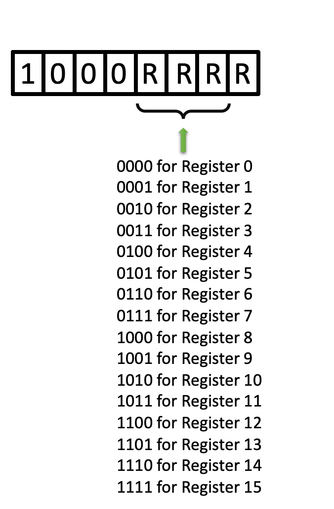
Binary |
1000 R |
Decimal |
128, then incrementing by 1 until 143 |
Hexadecimal |
0x80, then incrementing by 1 until 0x8F |
Symbolic |

|
Execution |
1 word, 8-bit code and an execution time of 10.8 \({\mu}\) sec |
Side-effects |
Depending on the result, the carry bit is reset or set. |
Implemented |
Detailed Description
The 4 bit content of the designated index register is added to the content of the accumulator with carry. The result is stored in the accumulator. The carry/link is set to 1 if a sum greater than 15 was generated to indicate a carry out; otherwise, the carry/link is set to 0. The 4 bit content of the index register is unaffected.
Example programs
/ Example program 1
        org    ram
        ldm    9
        xch    12
        ldm    6
        clc
        add    12
        end
In this example, the accumulator contains a value of 6, register 12 contains a value of 9, and the carry bit is 0.
Performing an ADD 12 (add the value of the accumulator to that in register 12) does the following:
Accumulator   =   0 1 1 0
Register 12   =   1 0 0 1
Carry         =         0
                ---------
Result      0     1 1 1 1
          Carry
The accumulator contains 15 and the carry bit is reset.
/ Example program 2
        org    ram
        ldm    9
        xch    12
        ldm    6
        stc
        add    12
        end
In this example, the accumulator contains a value of 6, register 12 contains a value of 9, and the carry bit is 1 - note the STC instruction replacing the CLC instruction.
Performing an ADD 12 (add the value of the accumulator to that in register 12) does the following:
Accumulator   =   0 1 1 0
Register 12   =   1 0 0 1
Carry         =         1
                ---------
Result      1     0 0 0 0
          Carry
The accumulator contains 0 and the carry bit is set.
